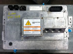
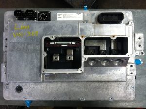
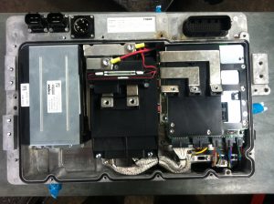
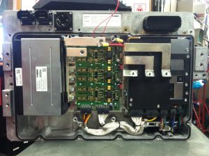
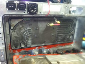
The Power Conversion Unit is home to many of the most important components of a Think. It is a big heavy aluminum box with a bunch of orange cables connected to it.
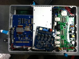
- On the front side from port to starboard (left to right, but right to left as viewed from the front):
- Bus bars to which the 3-phase motor cables bolt. And behind that:
- A circuit board with a bunch of microprocessors which I call the mother board.
- 2 current sensors for 2 of the 3 phases that power the traction motor.
- Bus bars to which the cables from the traction battery (frame wires) bolt.
- A magnetic switch that is closed by a magnet on the front cover. This is part of the Emergency Power Off circuit. And behind that:
- The Traction Inverter Module (TIM) which is an assembly that includes a control circuit board, spring contacts, insulated gate bipolar transistors (IGBTs), and hardware that mounts the IGBTs to a coolant channel. The TIM converts high voltage DC from the traction battery to 3-phase AC for the traction motor, and vice versa during regenerative braking.
- A big capacitor: 1000 microFarads. I think it would be accurate to say that this helps to correct the power factor of the motor which is a big inductor.
A coolant channel that flows through the middle.
On the back side from port to starboard:
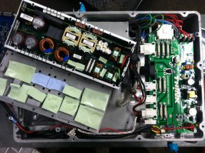
- A DC/DC converter (or DCM) which converts high voltage DC from the traction battery to low voltage DC for the 12 Volt systems on the car. On a conventional car an alternator does this job by taking energy from the engine through a belt.
- A charger, which converts line voltage from the EVSE to regulated high voltage to charge the traction battery.
- A “fuse card” which distributes high voltage and line voltage to the various components
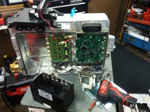
Now here it is in pictures:
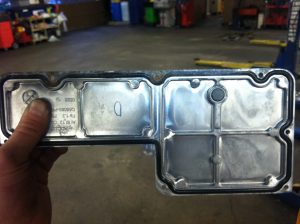
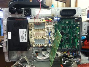
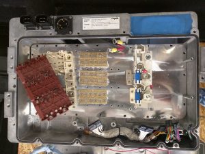
In the photograph below the IGBTs are in the center, mounted directly on the coolant channel. (In the image further below of the inside of coolant channel you can see heat sink fins directly on the opposite side of the IGBTs.) To the right of the IGBTs are the current sensors for 2 of the 3 phases. The the left of the IGBTs are the mounting brackets that bolt on top secure the DC and AC bus bars in contact with the IGBTs. The control circuit board for the IGBTs bolts on top of the reddish bracket. All this stuff together is what I refer to as the TIM.
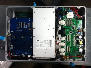
And here are some photos of the back side:
Sandwiched between the front and back components is a coolant channel. I have seen some leak into the inside of the PCU. Someone attempted to reseal the one below, but didn’t succeed:
