Long story short, I previously advocated in this post that fuses in the PCU should be replaced by higher rated fuses and the correctly rated fuses should be installed in the wire harness where they are easily accessible. I am amending that recommendation to say that the fuses inside the PCU should be removed and replaced with a simple jumper wire– no fuse at all inside the PCU, only one in the wire harness.
Why the change of heart? Because I’ve had one car return to find that the 25 Amp fuses inside the PCU blew before the 20 Amp fuses in the wire harness. I was utterly confounded by this, but after much head scratching I have a theory as to why is happened: I would like to think of fuses as devices that behave perfectly as we would expect them. For example, a 20A fuse would have virtually zero resistance and no chance of opening while operating at 20A and would open instantly when current rose to 20.001A. But they are really just bits of wire that are calibrated to melt under certain conditions. I found a good data sheet for one of the fuses I installed:
http://www.ferrazshawmutsales.com/pdfs/ATM.pdf
It shows a graph of the melting time for fuses plotted against electrical current. For just under 30A flowing through my 20A fuse it would take about 1000 seconds, about 15 minutes for the fuse to blow. At 70A it would take about 1s to blow, and at 250A only about 0.01s. The data sheet I found for the other fuses was less specific, saying only at 150% and 200% of rated current it would take a maximum of 30 minutes to blow. At 300% (75A) it would take a maximum of 10s to blow. All this data certainly makes some assumptions about voltage and ambient temperature; the temperature of the wire harness is probably usually lower that the temperature inside the PCU, or at least a bit different anyway. One fuse is a cartridge type, the other has leads and is soldered on to a printed circuit board– the heat transfer must be different for both. So with all the variability it just turned out that the higher rated fuse happened to blow first… Who would have guessed? Not me! The only conclusion I think we can draw from this is that it was a very high current event (as opposed to somewhere around 24A) that causes this failure.
There’s also the possibility that I affected the rating of the fuses when I soldered them. There are specifications about the soldering iron temperature settings, preheat time, soldering time, whether the fuse is compatible with wave soldering or other technologies. I tried to not get the fuses too hot while soldering them, but I didn’t use a heat sink on them or monitor my technique with respect to these newly found guidelines. The reason I’m fairly sure that I didn’t affect their rating is that both of the fuses on the circuit board were open; they must have been precisely matched for that to happen.
I know some of you Think owners (probably the ones who would spend their time reading a blog about their electric car) are electrical engineers, so I would appreciate if you have any input or feedback on this matter.
So here’s my original post:
I have no idea how it happens, but some Thinks blow a fuse inside the PCU which causes them to not be able to charge. Replacing a fuse would not be that big of a deal if it didn’t take 7 hours to remove and re-install the PCU in which they are mounted. Also, the fuse has leads that are soldered into through-holes on a circuit board, so it’s not exactly convenient like the blade-style fuses in the under-hood or under-dash fuse boxes of most cars.
The first few times we found this we thought it was a freak accident, so we just replaced the fuse with a new one of the same rating– we didn’t know how to prevent the fuse from blowing again… and we still don’t.
But having gotten much older and slightly wiser, we now install a retrofit to every PCU that comes out for any reason: The existing EVSE/charger fuses that are installed inside the PCU are rated 20 Amps (and I think at least 450V… whatever we replace it with meets or exceeds the existing voltage rating). We install 25 Amp fuses in their place inside the PCU, We install jumper wires (I use solid-core wire that’s about the same diameter as the fuse leads), and we also install 20 Amp fuses and water-tight inline fuse holders in the wire harness to the EVSE charge port near the coolant reservoir. The theory is that the 20 Amp fuses will always blow before the 25 Amp fuses (wrong!), and they will require much, much less labor to replace. And if the PCU ever gets removed and re-installed in a car that does not have inline fuses (though they should be labeled with a warning that they have been modified), hopefully 25 Amps will not exceed the rating so much that it will cause major damage.
If your Think is your only source of transportation (or if you have plenty of discretionary income) you might consider having this retrofit installed even if nothing else is wrong with your car.
So here are some details for technicians about how to install this EVSE fuse retrofit:
Remove the PCU from the car. (This is a topic unto itself.)
Label the outside of the PCU to ensure that it will be recognized as a having the modified fuses that require lower-rated inline fuses.
Remove the rear cover of the PCU (Torx 30).
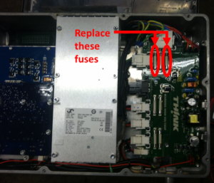
The fuse card is the green circuit board on the right side of the PCU. Most of the connectors can only be installed into one mating port on the fuse car. For those connectors that are not so obvious, make a note of where they connect to.
There are 3 clips that hold integrated circuits on the fuse card firmly again the PCU case as a heat sink. They simply press on and pull off. Remove them.
Disconnect the connectors from the fuse card.
Remove the bolts that secure the fuse card to the PCU (Torx 25, I think).
So now that the fuse card is removed from the PCU, you can remove the fuses and install the new ones. The fuses for the EVSE/charger are FU2 and FU3, which you might expect to be right next to each other, but they are not. FU1 is in between FU2 and FU3, they are labeled in silkscreen on the circuit board.
Now, I don’t know if the fuse card is a circuit board with internal layers or if it simply has copper traces on its front and back surfaces. So to be conservative I treat these through-holes as if they are connecting to internal layers of the circuit board. As such I remove the leads of the fuses from the through-holes as carefully as I can. I use a soldering iron to scrape away the clear conformal coating from the soldered joints and the surrounding areas on the front and back. I take my time adding lots of heat and solder to the joint to make sure it’s thoroughly melted through, and then I pry the fuse up with a small screwdriver.
I use a tool that I call a solder-sucker (I don’t know what it’s real name is– it’s just a spring loaded vacuum sucker thing) and flux with my soldering iron to remove all of the solder from the through-holes so that the new fuse leads wires will fit easily and the through-holes won’t be damaged.
Install the new fuses jumper wires and solder them on the front and back surfaces, making sure the work is heated enough that the solder flows freely. Remove excess solder. (In other words, use good soldering practices.)
Use an ohmeter to verify that you’ve installed the wires well. fuses well and haven’t overheated and burnt out the fuses in the process.
Re-install everything in reverse order of removal.
Now for the installation of the inline fuse holders and fuses:
(Obviously as you’re doing this you have the 12V battery disconnected (because you did that to remove the PCU), and you’re not plugged in to an EVSE (because you’re not an idiot).)
Remove the windshield wiper and rain tray at the bottom of the windshield.
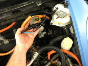
There’s plenty of extra slack in the EVSE wire harness which connects to the top of the PCU with a round connector. Disconnect it and work the harness in the orange convoluted wire loom down (toward the left side of the car and the EVSE port) through the zip-ties that secure it to the firewall. The seaman’s term for what you’re creating is a “bight.”
Carefully cut into the orange loom in the vicinity of the coolant reservoir and brake master cylinder.
Install the fuse holders to the thick blue and thick black wires keeping the following in mind:
Install the two inline fuse holders staggered in such a way that it will be impossible for anyone replacing the fuses to connect the wrong wires.
The fuse holders that I have used indicate one end to be on the load side (the PCU side of the wire harness). They also have insulation on the crimped portion, but I prefer to just cut that away (because it just gets torn up when you crimp it anyway) and use heat shrink with adhesive.
Assemble the fuse holder before crimping it on the wires to avoid forgetting to have the threaded collar/nut installed. (Don’t ask me how I came to have that suggestion.)
Put you’re heat-shrinkable tubing insulation on the wire before you crimp the fuse holder. (Not that I would ever forget this either…)
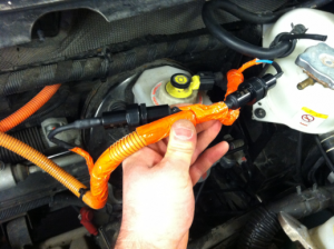
Leave the other wires in the orange loom and cut a notch out of the loom where the blue and black wires enter and exit the loom so that the cut edge of the loom won’t rub through the black and blue wires’ insulation.
I use orange tape to close up that portion of the loom that I have cut open.
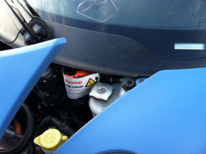
Install a warning sign on the loom so that no one will inadvertently expose themselves to high voltages while replacing the fuses.
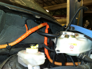
Tuck the wire harness with inline fuses up under the windshield where it will be most likely to stay dry.
Re-install the rain tray and windshield wiper.
I don’t understand:
AC charge fuses blowing? You are sure?
In both AC lines are fuses 20A. It’s supply for AC / DC converter AC100…240V to DC220…385V and then charging traction battery.
In one line from converter to traction battery is one 20A.
Max. current AC line in is 14A (my Think every time under 14A).
Extern 15A fuse possible. Modifikation 25A / 20A not needful.
If 20A fuse to battery blowing, it’s a fault current limiting in charger.
The named charger dates are AC/ DC 220-385V, 0-12,8A.
The battery electric circuit is an IT-grid (isolated earth).
Let us to revise:
Isolations fault printed board?
Characteristic of fuses (AC and HVDC charge)?
AC charge source properties?
Merci HANS GALLE
Yes, I am certain that the fuses are blowing as I have measured the fuses to be open circuits and returned many Thinks to proper operation by replacing them. I have no idea why the fuses blow; And I have no intention of trying to find the cause. (One of the only remaining bits of highschool German that I can remember because of frequent repetition is “Ich habe keine Ahnung.”) This phenomenon is not nearly so prevalent as MLEC precharge resistor failure.
I agree that there is a fault somewhere in the PCU/charging system or possibly in the EVSEs or grids attached to the failed cars or maybe even in the traction batteries. The intention is not to install a 25A fuse to accommodate proper operation. 25A is a somewhat arbitrary value for the fuse just as long as it’s rated higher than the inline fuse. The intent is that it never blow and that the inline 20A fuse maintain the specification that the manufacturer designed.
If you are confident that your AC line never flows more than 14A while operation normally I would highly recommend installing an 18A fuse inline (I use the example 18A because I have seen them available as I shopped online for fuses; 15A would work, too, of course.) This would guarantee that your easily installed/replaced 18A fuses blow before the 20A fuses that are very painful to replace.
If we can “prove” that every Think on every charger will not exceed 14A then I would recommend installing the inline fuse for everyone without modifying the fuse inside the PCU. My design simply attempts to avoid any situation where the inline fuse might blow while the system is operating properly. I know that some of the Think owners in my geographic area monitor their charging closely. I’d like to collect more data to make sure that there aren’t peak charging currents that exceed the average before recommending it to my customers, regardless of what the specification says.
As far as isolation faults, I have seen coolant leaks into PCUs and a water leak into the traction battery that caused isolation faults, but none of the PCUs with blown charger fuses had any moisture intrusion in the PCU. I don’t think water in battery would have caused it, especially without a flashing high voltage warning light, but I would never gamble on what I think.
AC charge source properties: Surely EVSEs include a surge protector, right? I don’t know, maybe not… Perhaps I should go back correlate the EVSE brands to the failed chargers. (I suspected that we already noticed that at least a few different EVSE brands and stopped taking note.)
I hope I’ve answered your questions– I’ve done my best. Your input is very valuable; I really appreciate it.
Sorry, today only I read your answer.
Surfed on elbilforum.no and came through ‘Think Tech Center’ to your Blog (What I am very interested).
It’s just great how you illuminate this issue.
To transfer externally 20A after is the better solution. Does not affect the protection of the aluminum box.
But your Fuse Holders are not responsible for AC100 … 240V!
In addition, protection against water and dust important (IP54 … 65), and shock protection by fuse replacement.
Perhaps stuck in heat shrink tubing?
Right, why 20A blow, we have to accept unexplained for now.
20A fuse is typ “fast blow”_ AC / DC converter could inrush_ … etc.
My house fuse is a miniature circuit breaker L-16A(for Line Protection). These have magnetic and thermal releases combined (Does USA also determined.).
The characteristic curves have an intersection at about 6 times the rated current. It is triggered because of 96A in about 5 seconds. At 1.4x the rated current no tripping.
So is neither protective nor of importance for the 20A fuse in the PCU.
I must go to try to measure over an hour the current profile for AC230V charge Inlet. Where I previously said it would under 14A.
Merci HANS
I think it is a surge or inrush current that blows the fuse. When electronic switching power supplies start to receive voltage, there is a very short time of high current to start up the power supply and charge the capacitors. The further away from the board, the less likely the fuse will blow due to the resistance of the wire up to the board (where the load is highest). I believe that putting the fuse holders as close to the PCU as possible and using 12 amp fuses (or 15 amp fast blow) (on the car that still has the 20 amp fuses on the board) will prevent the onboard fuses from blowing. I have been charging the car for several days with 12 amp fast blow fuses. So far they are working OK. I only charge on my home EVSE and monitor the current so I know when the car is charged. I believe some commercial EVSE units may actually charge at more than the 12 amps, but my car draws approximately 12-13 amps so that is where I started with the fuse size. If they blow in a week or two, I will go up to 15 amp fast blow fuses. Much easier than replacing the internal board fuses in the PCU. The sticker on the charger inside the PCU says 100-250 V @ 14 amps MAX and 25 amp fuse size. Remember that the pumps and fan while charging is added to this current. I don’t know if the power for the 12 volt supply is after these fuses, but from the schematic I suspect it is located after the 20 amp fuses. Why they put in 20 amp fuses to this charger when it states 25 amp fuse right on the charger sticker itself is beyond me…. and very painful to replace. I would definitely put inline fuse holders close to the PCU with 15 Amp fuses as a preventative measure, for 1 hour of labor and $20-40 in parts, you may save yourself 12 hours of painful PCU removal to jump across the fuses and add them later.
Johnny