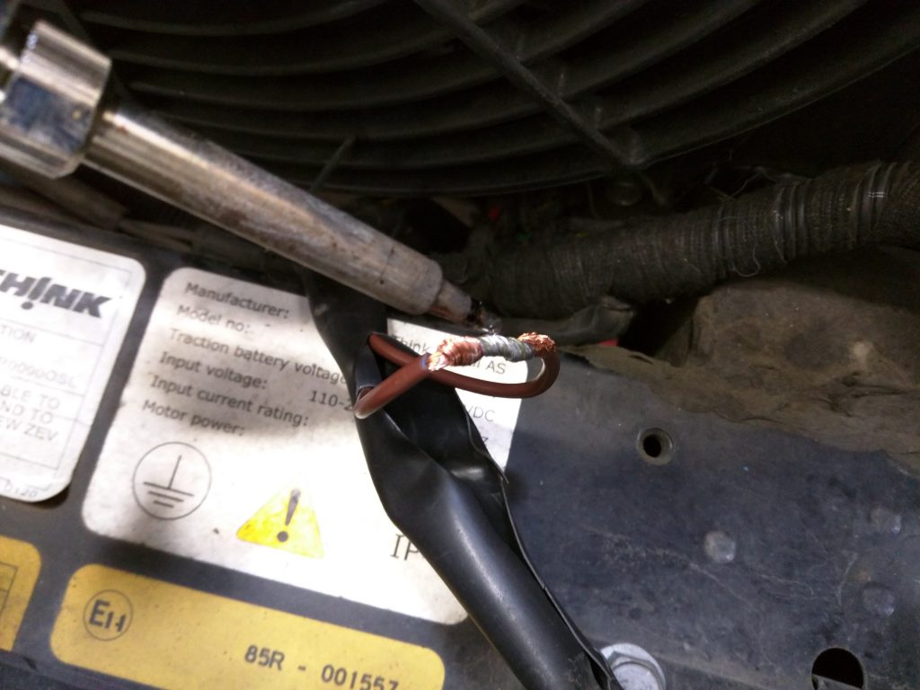
Based on an observation by Tom Goesch of ThinkParts4U and a Think owner, we’ve made a preliminary correlation between charger (or charger fuse) failure (internal to the PCU) and failure of the radiator fan low speed resistor. This is still a very new discovery, and I’m still thinking about the best course of action (and collecting better ideas from smarter people), but it’s in everyone’s best interest to get this issue checked out because the repair bill will exceed $1000 if you are so unfortunate as to be affected by it.
If you are car/electronics savvy, it’s not too difficult to test your radiator fans in both speeds. Please perform all of the following with the key turned off. Look forward in the passenger footwell and you will see a single bolt securing the relay box/bracket to the firewall. Use a 13mm socket/wrench to remove the bolt and pull the relay assembly down and aft. All the wires that enter the bottom side of the relay box come in from a few big harnesses on the right (starboard) side. There is one red wire that you should be careful to not to pull out that plugs into the front side of the relay box; this wire is part of the PTC retrofit as is the little white jumper wire that connects two terminals in the same relay socket.
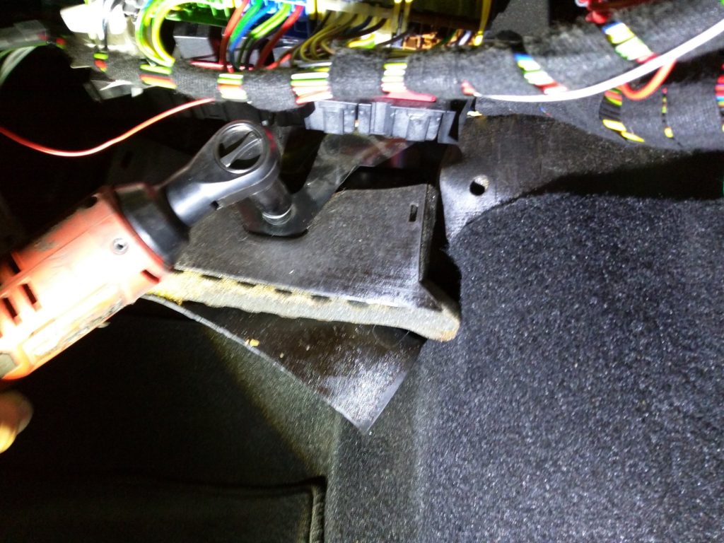
Remove relays 3 and 4. Relay pliers make this job much easier and less likely to damage the relays. You can consult the service manual Chapter G – Electrical 12V for a diagram of how the relays are arranged. Relays 3 and 4 are the large ones, second from the left. Relay 3 is the top, forward-most of the two and turns the fans on high speed. Relay 4 energizes the fans at low speed, through the suspect resistor.
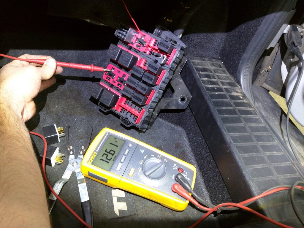
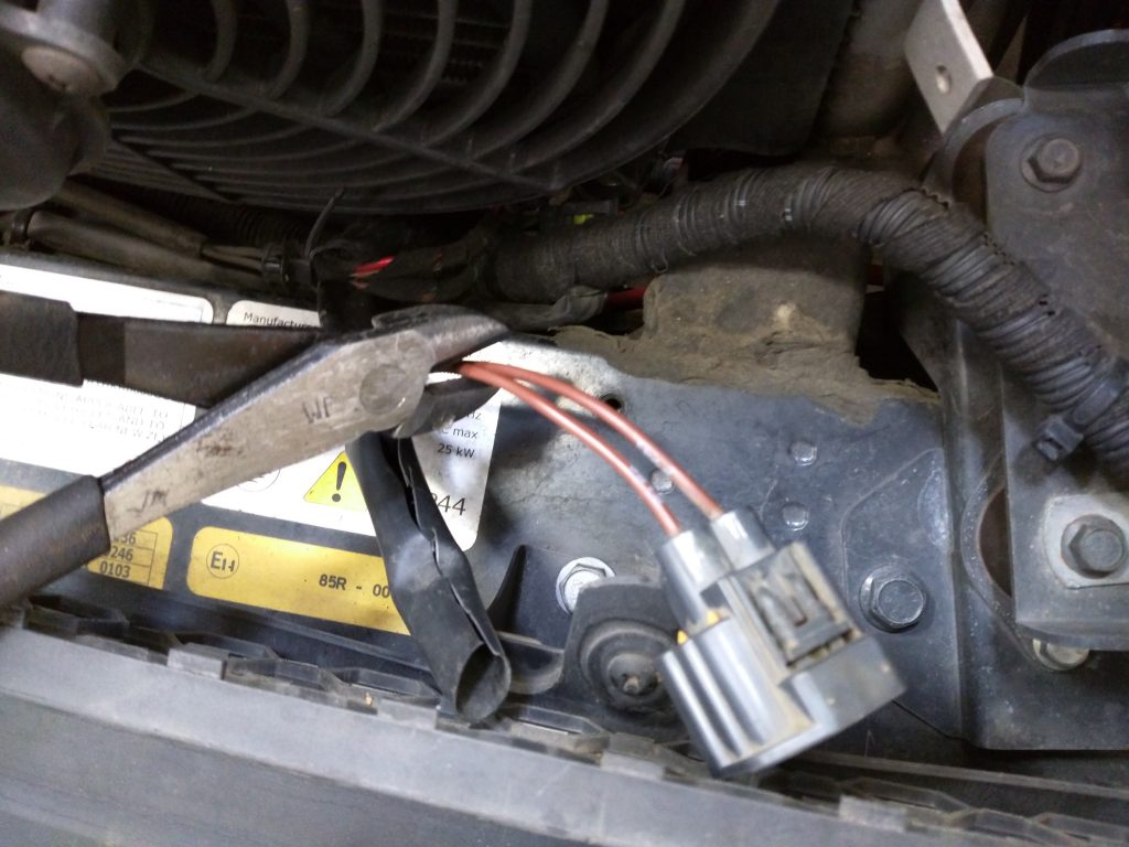
Use a jumper wire to connect the socket for pin 30 of the relay to ground; you can look at the labels on the bottom of the relay that you removed to reference which pin is which. The door latch/striker is not a reliable ground– sometimes it works, but sometimes it doesn’t. The door hinge is a better ground. In the image, I am using the leads of an ammeter to connect the circuit to ground because I was curious how much current the fans draw, but a plain old wire will do just fine. (And if you do use an ammeter that is fused for 10 Amps don’t leave it connected for long! If you do connect an ammeter and you measure a different current, it’s probably not a big deal because this 12.6 Amp spike was only during the first fraction of a second that I connected the circuit.)
(BTW, a relay only has 5 pins. I have no idea why the pins are numbered 30, 85, 86, 87 and 87a. It’s just weird.)
When you connect the socket for pin 30 of Relay 3 to ground you should hear the fans come on at high speed. It’s probably worth verifying visually that both fans are running; can hold a flashlight behind the radiator to see if the fan is spinning. (I think so anyway– I haven’t actually verified that.)
When you connect the socket of pin 30 for relay 4 you should hear the fans turn on at low speed. If you don’t hear them, then there’s a problem. And even if you do, you might have a problem in the future.
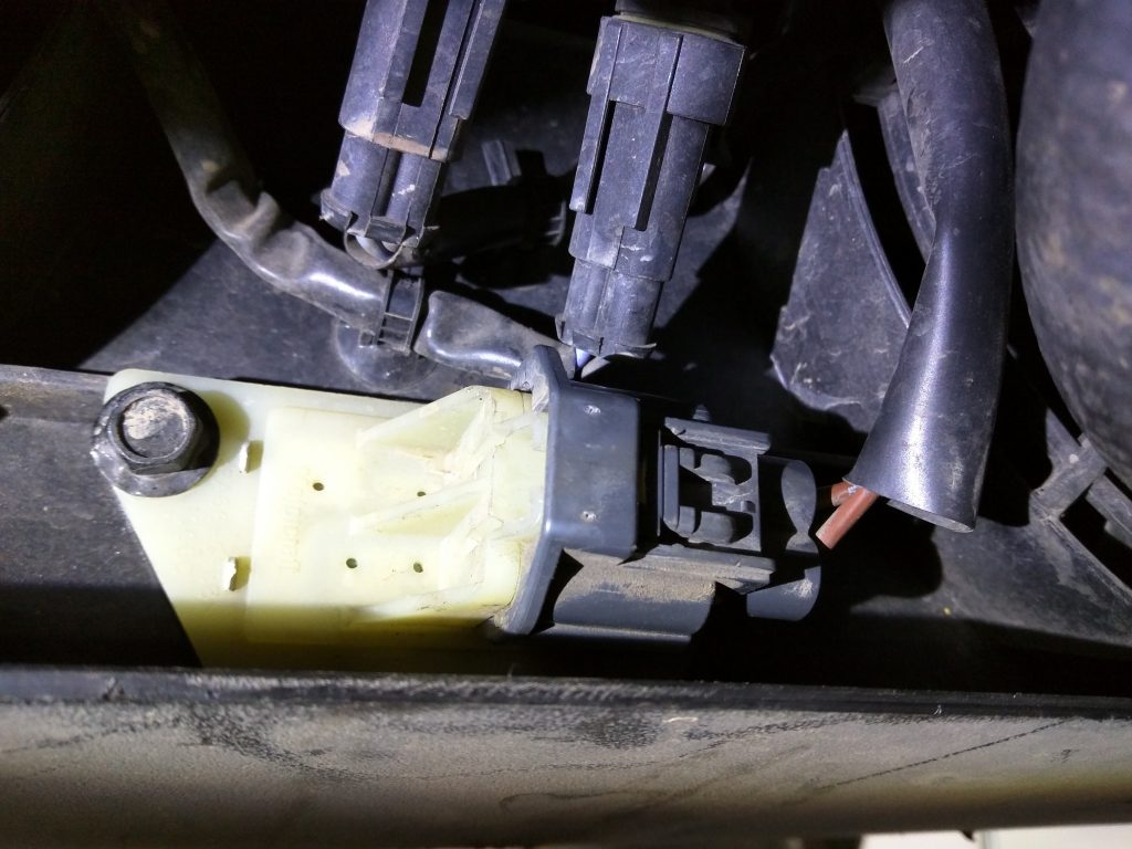
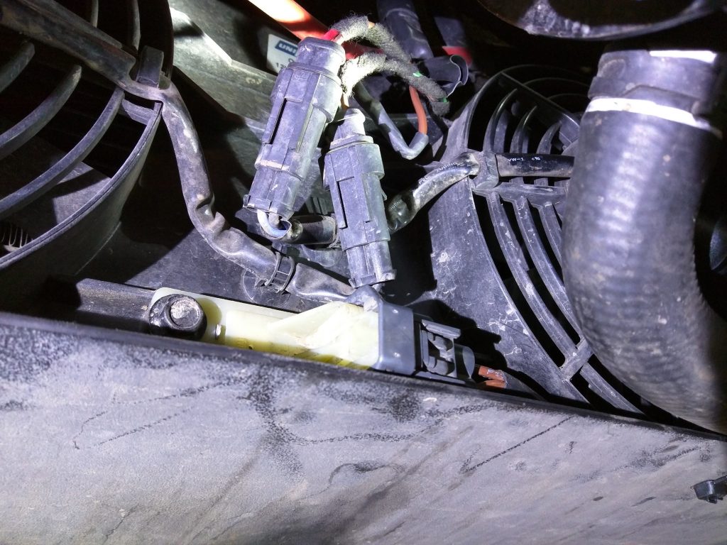
The radiator fan low-speed resistor is located at the bottom middle aft side of the radiator.
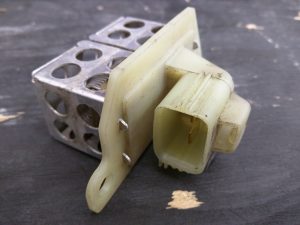
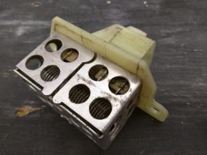
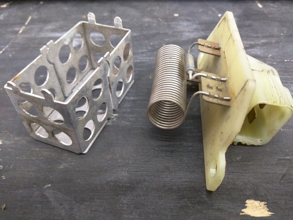
It consists of a plastic body with connector, a metal cage, a coiled conductor (in series) and the resistor itself. I don’t know why the pictured resistor failed, but the open circuit is across the resistor itself and not any of the other parts of the circuit. It doesn’t look very corroded, although Tom Goesch said that the one he saw was very corroded. As time goes on these resistors are only going to become more likely for fail.
My preliminary recommendation to prevent overheating due to radiator fans not turning on (and what I impelented on this car) is to simply bypass the resistor. I cut the two wires to the resistor, made something like a lineman’s splice, soldered and protected with heat shrink with adhesive on the inside for water resistance.
To do the repair I disconnected the two radiator fan connectors and pulled the wire harness up in front of the condenser where it was easily accessible from above. I left a short pig-tail on the resistor conenctor in case I might need to reconnect to it some day for some unanticipated reason. (So even though you can see connector plugged in to the resistor with wires leading away in the last photo, the wires are cut just an inch beyond what is visible, in shrink wrap just to be tidy. The bypass circuit is above, next to the radiator fan connectors.) With this fix the radiator fans will no longer operate at low speed; when the PCU thinks it’s turning the fans on at low speed they will actually be on high speed. I think the only negative consequence of this is that the fans are significantly louder at high speed.
Be sure to verify your repair by testing with the same method above.
